Flexible PUR Sheathed Oil & Tear Resistant Control Cable
Flexible Oil & Tear Resistant PUR Sheathed Control Cable Application
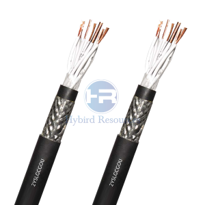
The especially Flexible Oil & Tear Resistant PUR Sheathed Control Cable, YSL11Y provides an excellent chemical and abrasion resistance as well as being tear-resistant and halogen-free with low flame propagation. For use in harsh environments. This Flexible PUR Control Cable is also intended for use in heavy-duty industrial applications where flexibility and heavy wear and tear are required. The PUR sheath makes this cable ideal for use in the machine tools, plant manufacturing, and power circuits because of it’s extreme durability.
Flexible Oil & Tear Resistant PUR Sheathed Control Cable YSL11Y Construction
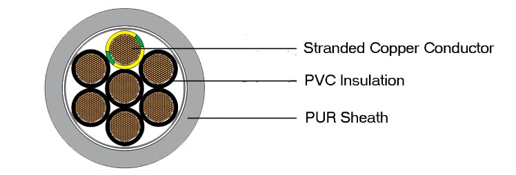
| Conductor: | Bare, flexible stranded copper |
| Stranding: | According to VDE 0295 class 5, IEC 60228 |
| Insulation: | Black PVC, number coded, G / Y earth |
| Outer Sheath: | PUR Grey, RAL 7001, microbe and hydrolysis resistant,adhesion free, flame retardant |
Flexible Oil & Tear Resistant PUR Sheathed Control Cable Technical Data
| Voltage: | Working:300/500V Test:2000V |
| Temperature Range: | Flexing:-5°C to +70°C Static:-40°C to +70°C |
| Bending Radius: | 12.5 x Ø |
Flexible Oil & Tear Resistant PUR Sheathed Control Cable Specification
| Number of cores and | Approx. outside diameter | Copper weight | Approx. weight |
| mm2 per conductor | mm | kg/km | kg/km |
| 2 x 0.5 | 5.9 | 10 | 39 |
| 3 G 0.5 | 6.2 | 14 | 46 |
| 4 G 0.5 | 6.9 | 19 | 56 |
| 5 G 0.5 | 7.4 | 24 | 65 |
| 7 G 0.5 | 9.1 | 34 | 92 |
| 12 G 0.5 | 11.3 | 58 | 149 |
| 18 G 0.5 | 13.2 | 86 | 207 |
| 25 G 0.5 | 15 | 120 | 274 |
| 34 G 0.5 | 18.7 | 163 | 392 |
| 41 G 0.5 | 20 | 197 | 458 |
| 2 X 0.75 | 6.4 | 14 | 48 |
| 3 G 0.75 | 6.8 | 22 | 58 |
| 4 G 0.75 | 7.4 | 29 | 67 |
| 5 G 0.75 | 8.6 | 36 | 88 |
| 7 G 0.75 | 10 | 50 | 119 |
| 12 G 0.75 | 12.4 | 86 | 193 |
| 18 G 0.75 | 14.4 | 130 | 269 |
| 25 G 0.75 | 17.2 | 180 | 378 |
| 34 G 0.75 | 20.4 | 245 | 508 |
| 41 G 0.75 | 22 | 295 | 598 |
| 2 x 1.0 | 6.8 | 19 | 57 |
| 3 G 1.0 | 7.2 | 29 | 69 |
| 4 G 1.0 | 8.2 | 38 | 90 |
| 5 G 1.0 | 9 | 48 | 107 |
| 7 G 1.0 | 11.1 | 67 | 151 |
| 12 G 1.0 | 13.2 | 115 | 233 |
| 18 G 1.0 | 15.4 | 173 | 328 |
| 25 G 1.0 | 19 | 240 | 479 |
| 34 G 1.0 | 21.8 | 326 | 616 |
| 41 G 1.0 | 23.4 | 394 | 727 |
| 2 x 1.5 | 7.4 | 29 | 73 |
| 3 G 1.5 | 8.3 | 43 | 96 |
| 4 G 1.5 | 9 | 58 | 118 |
| 5 G 1.5 | 9.8 | 72 | 140 |
| 7 G 1.5 | 12.2 | 101 | 197 |
| 12 G 1.5 | 14.5 | 173 | 309 |
| 18 G 1.5 | 17.6 | 259 | 458 |
| 25 G 1.5 | 20.7 | 360 | 635 |
| 34 G 1.5 | 24.6 | 490 | 851 |
| 41 G 1.5 | 26.3 | 590 | 1003 |
| 3 G 2.5 | 9.7 | 72 | 142 |
| 4 G 2.5 | 11 | 96 | 184 |
| 5 G 2.5 | 12.1 | 120 | 220 |
| 7 G 2.5 | 14.2 | 168 | 294 |
| 12 G 2.5 | 17.8 | 288 | 489 |
DISCLAIMER: This is just part of the standard parameters of our products. Please contact our Engineer if you need more. And the information contained within this webpage is for guidance only and is subject to change without notice or liability. All dimensions and specifications are nominal and are subject to normal manufacturing tolerances. All pictures shown are for illustration purposes only. The actual product may vary. All the information is provided in good faith and is believed to be correct at the time of publication.